Computer Aided Drafting
“switch” it up
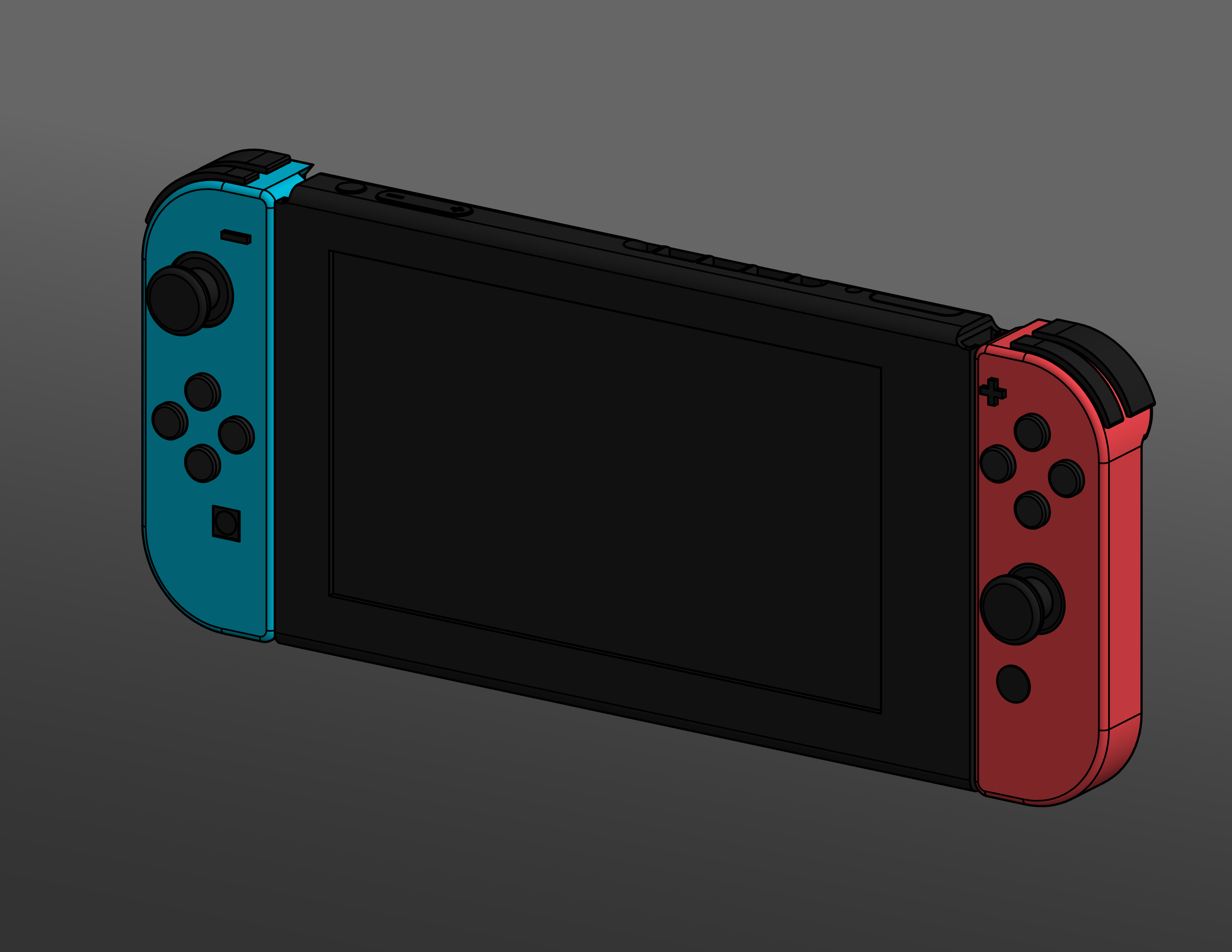
Switch Assembly
An assembly of Nintendo’s latest console, the Switch. The components all have accurate dimensions, which were measured with calipers and a ruler. The Drawing was then imported into Adobe Illustrator to be Enhanced for presentational use.
Tools used:
Sketching:
Sketch constraints (coincident, parallel, vertical/horizontal, equal, concentric, etc.)
Geometry tools (line, spline, arc, circle, slot, rectangle, fillet, etc.)
Geometry projection
Part modeling:
Geometry creation (extrude, revolve)
Geometry modification (fillet, chamfer)
Work feature creation (offset planes, angled planes, midplanes)
Multibody part creation and derived components
Assembly:
Placement of components
Constraining base component relative to origin planes/axes
Grounding of base component
Copying and pasting of parts
Constraining of parts (flush, offset, concentric, etc.)
Presentation:
Creation of “exploded” views (component tweaking, new snapshot view creation)
Drawings:
View placement (base view, projected views, presentation views)
View manipulation (changing orientation, tangent edge visibility)
Adding dimensions and notes with leaders
Editing sheet details (changing sheet size, titleblock fields)


The Six Pack
An assembly of a sheet metal 6 pack container, complete with 12oz bottles and bottle caps. Design for the sheet metal 6-pack holder partially based on a deconstructed cardboard 6-pack holder, with some modifications made for sheet metal design. Bottle and cap dimensions are accurate, and were obtained with calipers.
Tools used:
Sketching:
Sketch constraints (coincident, parallel, vertical/horizontal, equal, concentric, etc.)
Geometry tools (line, spline, arc, circle, slot, rectangle, fillet, etc.)
Geometry modification (trim, offset)
Geometry projection
Sketch patterns (rectangular, circular, mirror)
Part modeling:
Geometry creation (extrude, revolve, loft)
Geometry modification (fillet)
Work feature creation (offset planes, angled planes, midplanes)
Multibody part creation and derived components
Sheet metal tools:
Geometry tools (face, flange, hem, fold)
Altering sheet metal defaults
Modifying/overriding bend allowances
Assembly:
Placement of components
Constraining base component relative to origin planes/axes
Grounding of base component
Part and sub-assembly patterns
Constraining of parts (flush, offset, concentric, etc.)
Presentation:
Creation of “exploded” views (component tweaking, new snapshot view creation)
Drawing:
View placement (base view, projected views, detail views, presentation views)
View manipulation (changing orientation, tangent edge visibility)
Adding BOM and balloons for parts
Adding dimensions and notes with leaders
Editing sheet details (changing sheet size, titleblock fields)
BOM management:
Modification of iProperties for BOM part numbers and descriptions
Understanding of BOM overrides


